Lets get started communicating through Modbus RTU using SAFE as a master and your device as a slave. In this guide I will show you on how to setup your Modbus RTU communication in SAFE, how to write a request, and how to read the response.
Connect your computer and Modbus device
Before you start you should connect your Modbus device to your computer via an USB-to-Serial converter and ensure that any driver necessary is installed. Usually it will be installed automatically. There are usually multiple lines on the converter so read the Modbus device manual on how to properly connect the Modbus.
You can maybe also find a little help with connecting the wires correctly here
Create a blank SAFE project
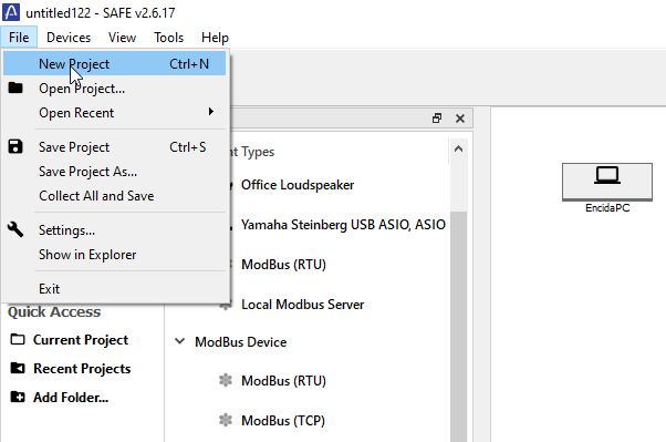
When the device and computer has been connected, open SAFE and create a new project in the menu under File --> New Project in the top left corner. Then create a blank project.
Configure your Modbus device
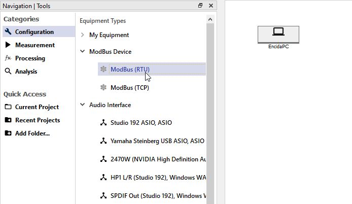
To configure you Modbus RTU device click and drag a ModBus (RTU) onto the board. You can find it in your Equipment Types under ModBus Device.
With the Modbus device on the board click it. To your right you can see the device properties. Here you can name the device and it is here we need to configure it.
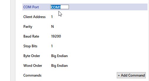
Under the Modbus device properties you must select the correct COM port and correct protocol settings. This includes Client Address, Parity, Baud Rate, Stop Bits, Byte Order, and Word Order.
NOTE: if there is no cable between the device and the computer on the board the physical connection is probably not correct. Check your device manager to see if it has been connected
You should be able to find all of these settings in the manual for the Modbus device. If this is not possible contact the vendor or Encida for further assistance.
Adding Modbus Commands
With the Modbus protocol set you are now able to start adding commands which is the request the PC will send to the device. In the Modbus instructions set you can find every command your device has but usually you dont use them all. So in SAFE you have the opportunity to add the ones you need and give them an easy name instead of having to remember all the different addresses.
To add commands click the + Add Commands button in the properties. An Add New Command Menu will pop-up. In this menu you can define a bunch of different settings for you command but the obligatory settings are Register Address, Register type, Value type, and Name.
The Register Address is a HEX number specified in the Modbus address manual and is different from command to command. Register type is the specification of the type of register. A holding means it is an read/write register, while an input means its an read only register. The Value type defines what type of value you are expecting from the register. If you choose a value type of 32 bits 2 registers will be read from the device, the address you define and the next address. The Name is just a name that is recognisable to you. You can also specify a Default value that the holding register should write if not changed.
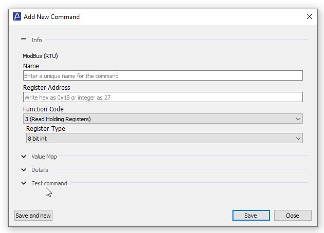
To check if the command is valid open the Test Command and Pres Test command If the response is what you expect then click Save or Click Save and new if you want to add more commands in the same way as before.
Using write commands
To write and read commands you must go to the the category "Measurement". You do this all the way to the left by clicking on Measurement. Now you can see your empty procedure with a single step. In order for the procedure to do something you must drag a measurement tool into a step. Start by opening the ModBus Tools, and click and drag out the Macro track into step 1. In Step 1 the Macro track will now show.

To use one of the commands you added in the previous step press the Add command button in the track you just inserted. Here you will see a list of all the commands you added so just select one or more of them. This will make sure that the PC will send out the commands when the test is started and this step is running.
All commands default to read. If you want to write a value to a holding register, change the Read/Write and Value property in the properties window.
A step will by default have a measurement time of 5 seconds which you can change by clicking on the step and changing the measurement time in the properties window to the right. You can also drag in multiple tracks or create more steps but we will skip this for now.
Starting a test
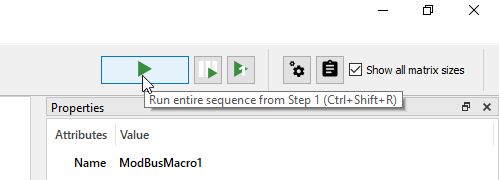
To start a test click the big play button in the top right corner and wait until the measurement is done.
1, 2, 3, 4, 5..
You have now performed your first test with Modbus RTU!
Checking device response
If you have some kind of transducer or controller as your Modbus device you should see it reacting to your request. However you can also open the Data Management menu under Tools in the menubar or press Alt-Shift-D to open. Here you will se any response the device sends.